Julia Sakalus
pong bot
March 2020
Task
Design a LEGO contraption to throw a ball into a cup
The trial and error
PongBot 1.0 (image on left) looked very different from the final GirrafferBot. A partial picture of this iteration remains. It had one motor to control a long lever arm, and another motor that controlled the angle of launch. After testing out this iteration a couple of times, I quickly decided it needed to be changed -- the ball did not go far enough and it wouldn't fly very straight.
PongBot 2.0 - 2.3 were a build off V1.0 -- the lever arm got geared down to make it go faster, the angle at which it was positioned was changed (hitting the ball from the bottom vs the side/top), there was an attempt to move the angle of the arm together with the angle of the launch ramp, and rubber wheels were added onto the end of the lever to increase contact surface area with the ball. None of these approaches produced a satisfactory result in terms of the desired distance to be travelled. Something completely different had to be done. This led to the birth of PongBot 3.0.

The Solution: PongBot 3.0
Through the above iterations it was discovered that the angle of launch did not play a great effect in the distance travelled by the ball, and neither did the gearing. The motor that was being used to control the angle of launch was then stripped and repurposed where it could really make a difference -- physically moving the robot closer. To add some more zing and HEIGHT to the little bot, a third motor was added that would grant control of the direction of launch. At this time, PongBot 3.0 officially got the nickname GirrafferBot.
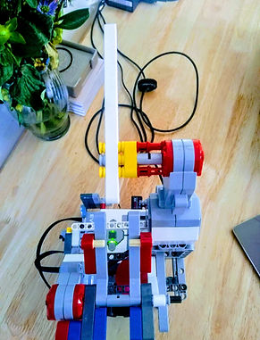
The Design
GirafferBot is made out of LEGO's, with it's brains being the EV3 brick. It uses an ultrasonic sensor to measure the distance between itself and and a cup, and three different motors to control its swinging arm, its forward and backwards position relative to the cup in front of it, and its direction of launch (demonstrated in the video on the right).
SystemLink
Cloud capability was added to the robot that allows the remote control of when it launches the ball, as well as changes in the direction of launch.

The Models
Physics Model
I measured the height of the launch ramp, the height of the cup, and the angle of the launch ramp. I then used these values in the following projectile motion equations:
x = v*cos(θ)*t
y = y0 + v*sin(θ)*t - 1/2*g*t^2
where x is the horizontal distance travelled, v is the initial velocity, θ is the angle of launch (= 50°), t is the time in air, y is the difference in height between launch point and land point (= 8in = 20.32 cm) , y0 is launch height (= 0 in), and g is acceleration due to gravity ( = 980cm/s/s).
By combining these two equations I eliminated t, and was able to solve for v.
The equation I got was
v = ((1.14*10^6)*x)/ sqrt(1306000075*x + 22267960163)
* thank you WolframAlpha for doing this math for me
Since the motor runs in a circular motion, this linear velocity needed to be converted to angular velocity, which was done by diving the whole equation by the length of flinger arm = 3in = 7.62 cm according to the relationship ω = v/r. This produced the final relationship:
v = (((1.14*10^6)*x)/ sqrt(1306000075*x + 22267960163)) / 3
The x in this relationship was the distance between the robot and the cup it was aiming into, and the v is used to control the power of the motor.
In 25 trials between 3 and 30 cm, this model had a 100% accuracy. Above 30cm the ultrasonic sensor was not always detecting the correct distance, so these cases were not tested.
AI Model
The AI model was created by pre-setting the power of the motor, and manually running 15 trials for powers of 20 through 100, going up by 10 each time. The distance to the cup (if the robot made it in) was recorded against the power that it was launching the ball with, and a plot of this data was made. The data appeared to be a linear fit, and the generated linear regression model was input into the robot's brain. The graph and the equation are shown to the right.
In 50 trials between 3 and 30 cm, this model had a 94% accuracy, with the three misses happening at distances > 28cm.
.png)
The Code: Basic Run-Down
The code controls the robot.
First, several functions are defined that allow access to and making changes to variables ("Tags") in SystemLinks. These allow for controlling the robot directly from the ~cloud~.
Next, all the motor and sensor ports are defined, and the SystemLink variables are reset to a default.
After all the initialization is complete, the robot enters an infinite loop, where all the magic happens:
-
Flinger (the thing that flings the ball) finds its reset position
-
Another while loop is entered. Here the robot is waiting for either the button on its back to be pressed, or for the button on SystemLink to be pressed. Once thsi button is pressed, robot exits loop and moves on to step 3:
-
Robot checks the ultrasonic distance sensor values. If the value is equal to 2550, this is likely an error - this occurrs most often when an object is too close. If the bot detects an object that is more than 300mm (30cm) away, it moves until it is 280 cm away from that object.
-
Wheels lock in place.
-
Robot calculates the necessary power of the flinger based on the distance away from object.
-
There is both a physics model, calculated using projectile motion, and an AI model, made by creating training data and making a linear regression plot.
-
-
If the calculated power is less than 30, robot sets it equal to 30 because otherwise it is not powerful enough to launch ball
-
Several values are printed to the terminal screen, helpful in debugging as well as creating training data.
-
Robot returns to beginning of infinite loop.